2022 posts
To talk to my IC-7610 via wireguard, I set up UDP port forwarding for ports 50001 50002 50003 on a raspi:
domain (ip) {
  table filter {
    chain FORWARD {
      policy ACCEPT;
    }
  }

  table nat {
    chain PREROUTING {
      interface (wg0) {
        proto udp dport 50001 DNAT to 192.168.0.6;
        proto udp dport 50002 DNAT to 192.168.0.6;
        proto udp dport 50003 DNAT to 192.168.0.6;
      }
    }

    chain POSTROUTING {
      outerface (eth0) {
        proto udp dport 50001 SNAT to-source 192.168.0.3;
        proto udp dport 50002 SNAT to-source 192.168.0.3;
        proto udp dport 50003 SNAT to-source 192.168.0.3;
      }
    }
  }
}
LoRa APRS iGate
The official documentation of https://github.com/lora-aprs/LoRa_APRS_iGate uses the PlatformIO plugin of MS Visual Studio Code. Here are the commands to get it running without the GUI:
git clone https://github.com/lora-aprs/LoRa_APRS_iGate.git
cd LoRa_APRS_iGate
- Edit data/is-cfg.json with your station info
- Edit platformio.ini:
board = ttgo-lora32-v21
pip3 install platformio

pio run
...
Building .pio/build/lora_board/firmware.bin
...

pio run --target upload
...
Uploading .pio/build/lora_board/firmware.bin
...

pio run --target uploadfs
...
Building SPIFFS image from 'data' directory to .pio/build/lora_board/spiffs.bin
/is-cfg.json
...
Uploading .pio/build/lora_board/spiffs.bin
...
LoRa APRS Tracker
The procedure for the tracker is the same, but the GPS module might need a reset first:
git clone https://github.com/lora-aprs/TTGO-T-Beam_GPS-reset.git
cd TTGO-T-Beam_GPS-reset
pio run -e ttgo-t-beam-v1
pio run --target upload -e ttgo-t-beam-v1
# screen /dev/ttyACM0 115200
... and then upload https://github.com/lora-aprs/LoRa_APRS_Tracker.git
Classic ham radio transceivers have physical connectors for morse keys and microphones. When the transceiver is a software defined radio (SDR) device, voice operation is easy by attaching a headset, but solutions to connect a morse key, be it a straight key or paddles, to a modern PC are rare. In the old times, machines had serial ports with RTS/DTR lines, but these do not exist anymore, so a new interface is needed.
I am using a LimeSDR as ground station for the QO-100 satellite, and naturally also wanted to do CW operation there. I started with SDRangel which has a built-in morse generator, but naturally wanted to connect a CW key. At first sight, all the bits are there, there's a tune button that could be used as a straight key, as well as keyboard bindings for dots and dashes. But the delay key->local audio is almost a full second, so that's a no-go. I then went to hack my K3NG keyer to output ^ (high) _ (low) signals on the USB interface, and have a smallish Python program read that and send SDRangel REST API requests. Works, but that solution always felt "too big" to me, plus the sidetone from the buzzer inside the Arduino case could be heard in the whole house. And the total TX-RX delay was well over a second.
Next I tried building some GNU Radio flowcharts to solve the same problem but which all had the same trouble that the buffers grew way too big to allow the sidetone to be used for keying. At the same time, I switched the transceiver from SDRangel to another GR flowchart which reduced the overall TX-RX delay to something much shorter, but the local audio delay was still too slow for CW.
So after some back and forth, I came up with this solution: the external interface from the CW paddles to the PC is a small DigiSpark board programmed to output MIDI signals, and on the (Linux) PC side, there is a Python program listening for MIDI and acting as a iambic CW keyer. The morse dots and dashes are uploaded as "samples" to PulseAudio, where they are played both on the local sidetone channel (usually headphones) and on the audio channel driving the SDR transceiver. There is no delay. :)
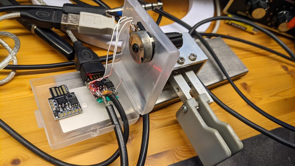
DigiSpark hardware
The DigiSpark is a very small embedded computer that can be programmed using the Arduino toolchain.
Of the 6 IO pins, two are used for the USB bus, two connect the dit and dah lines of the CW paddle, one connects to a potentiometer for adjusting the keying speed, and the last one is unconnected in this design, but could be used for keying a physical transceiver. (The onboard LED uses the this pin.)
            +---------------+
            |            P5 o  -- 10k potentiometer middle pin
        =====  Attiny85  P4 o  -- USB (internal)
   USB  -----            P3 o  -- USB (internal)
        -----            P2 o  -- dah paddle
        =====   78M05    P1 o  -- (LED/TRX)
            |            P0 o  -- dit paddle
            +---o-o-o-------+
There is an extra 27 kΩ resistor in the ground connection of the potentiometer to keep the P5 voltage > 2.5 V, or else the DigiSpark resets. (This could be changed by blowing some fuses, but is not necessary.)

The Arduino sketch for the keyer uses the DigisparkMIDI library. The code is quite simple: if the paddles are pressed, send a MIDI note_on event (dit = note 1, dah = note 2), when released, send note_off. When the potentiometer is changed, send a control_change event (control 3), the value read is conveniently scaled to wpm speed values between 8 and 40.
    if (dit)
      midi.sendNoteOn(NOTE_DIT, 1);
    else
      midi.sendNoteOff(NOTE_DIT, 0);

    if (dah)
      midi.sendNoteOn(NOTE_DAH, 1);
    else
      midi.sendNoteOff(NOTE_DAH, 0);

    if (new_speed != old_speed)
      midi.sendControlChange(CHANNEL_SPEED, new_speed);
The device uses a generic USB id that is recognized by Linux as a MIDI device:
$ lsusb
Bus 001 Device 008: ID 16c0:05e4 Van Ooijen Technische Informatica Free shared USB VID/PID pair for MIDI devices

$ amidi -l
Dir Device    Name
IO  hw:2,0,0  MidiStomp MIDI 1

$ aseqdump -l
 Port    Client name                      Port name
 24:0    MidiStomp                        MidiStomp MIDI 1

$ aseqdump --port MidiStomp
Source  Event                  Ch  Data
 24:0   Control change          0, controller 3, value 24
 24:0   Note on                 0, note 1, velocity 1
 24:0   Note on                 0, note 2, velocity 1
 24:0   Note off                0, note 1, velocity 0
 24:0   Note off                0, note 2, velocity 0
 24:0   Control change          0, controller 3, value 25
 24:0   Control change          0, controller 3, value 26
Python and PulseAudio software
On the Linux host side, a Python program is listening for MIDI events and acts as a iambic CW keyer that converts the stream of note on/off into CW signals.
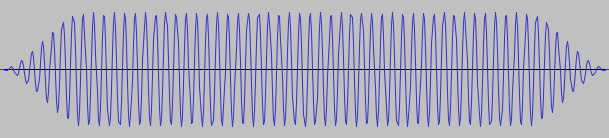
Instead of providing a full audio stream, dit and dah "samples" are uploaded to PulseAudio, and triggered via the pulsectl library. On speed changes, new samples are uploaded. The samples are played on two channels, one for the sidetone on the operator headphones, and one on the audio input device for the SDR transmitter.

The virtual "tx0" audio device can be created on boot using this systemd config snippet:
# $HOME/.config/systemd/user/pulseaudio.service.d/override.conf
[Service]
ExecStartPost=/usr/bin/pacmd load-module module-null-sink sink_name=tx0 sink_properties=device.description=tx0
The CW text sent is printed on stdout:
$ ./midicwkeyer.py
TX port is tx0 (3)
Sidetone port is Plantronics Blackwire 3225 Series Analog Stereo (7)
 CQ CQ DF7CB
Download
Needless to say, this is open source: https://github.com/df7cb/df7cb-shack/tree/master/midicwkeyer